Forensic Engineering

A Few Corrections To Avoid Hideout Effects

A Few Corrections To Avoid Hideout Effects

Problem Experienced

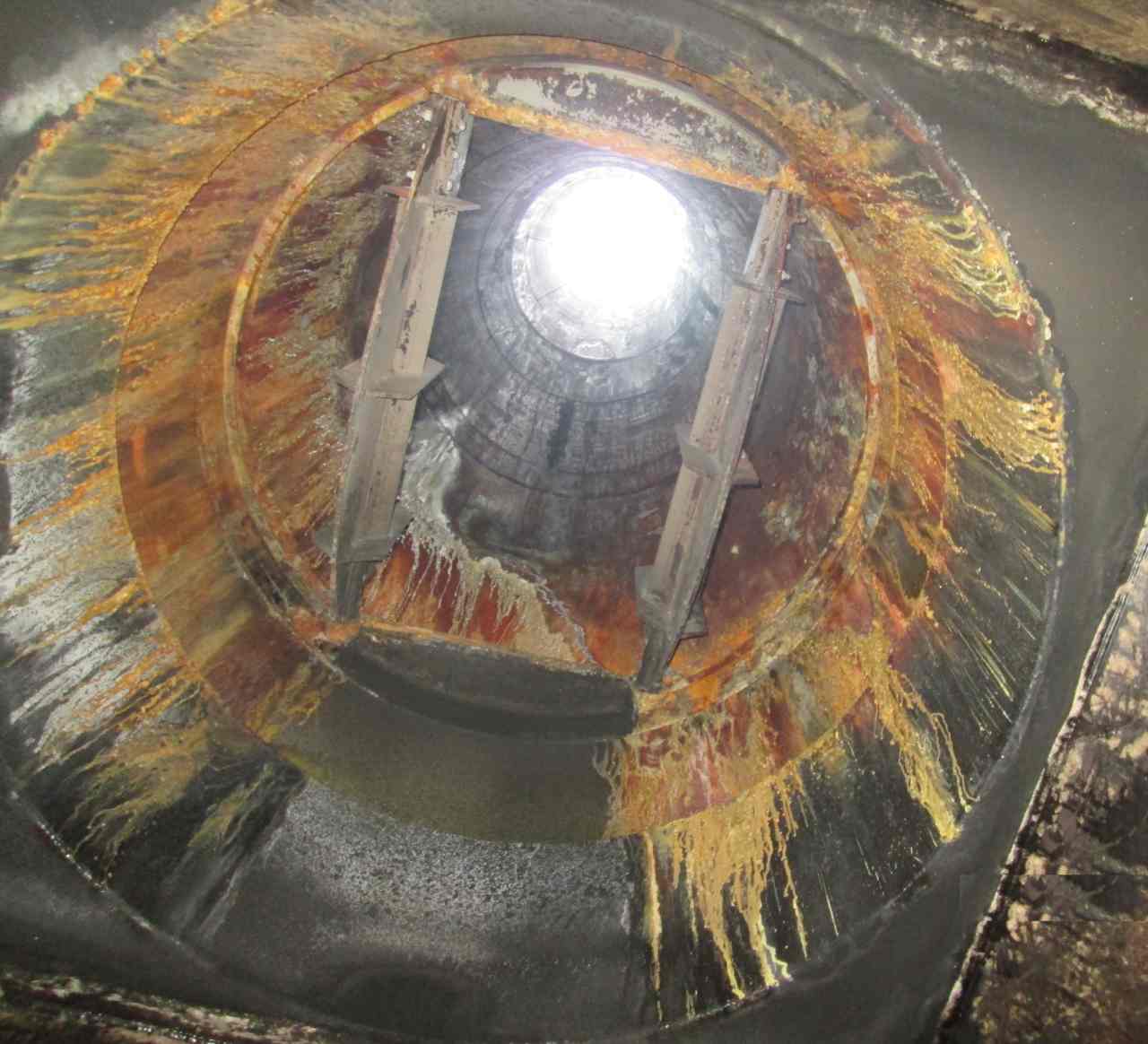
The phenomenon of scaling is a type of fouling typically observed in heat exchangers, steam generators and cooling systems. It is caused by the interaction of chemical species dissolved in the water to form inorganic salts.

The most common species which bring about the formation of scales are calcium and sodium-based compounds. The solubility of theses salts is temperature and pH dependent and it is somewhat sensitive to possible variations. In some cases, they can present several points of low solubility and create hideout effects in transitory conditions.

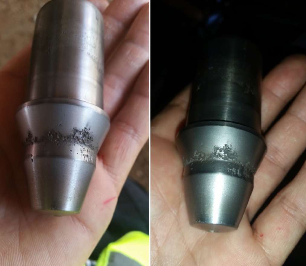
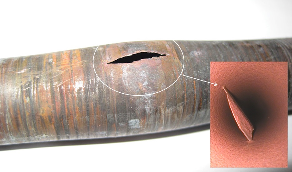
That is the case we have recently observed in a power plant due to phosphate hideouts which was noticed during the daily startup. Phosphate hideout is the result of chemical reactions of sodium phosphate with iron oxides where the reaction products has low solubility in high operating conditions.  As consequence, salt precipitation occurs. However, at lower loads and heat fluxes, these precipitates will undergo hydrolysis and return to solution. If the problem is not properly identified, these scales of phosphates can lead to various issues which are mainly loss of pressure drop, resistance to heat transfer and erosion-corrosion.

Technical Approach

We were able to solve the problem by implementing a few corrections based on the following approach:

  • In an attempt to control the effects of phosphate hideouts and scale formations, it was required to perform some changes the chemical treatment program. The first approach was to dose a mixture of tri-sodium and di-sodium phosphate which reduces the amount of sodium and therefore, minimizes the risk of carryovers. Another possibility that was tested required the dosing of Trisodum Phosphate which helps to control any possible acid attack. But it was difficult to maintain the equilibrium. Given the nature of the process conditions, we decided to go with All Volatile Treatment.
  • An optimization of the hydraulic of the system was necessary to enhance fluid velocities and flow distribution. These parameters has a direct influence in the rate of deposition; therefore, this analysis gave as the possibility to create a map of zone with high probability of accumulation of scales.
  • High Reynolds numbers must be achieved by installing of swirling devices. This ensured the correct grade of turbulences and the right chemical mixing during dosing. In addition, some of the dosing points where changed to a more appropriate location.
  • Solubility and reactivity of chemical compounds is primary governed by temperature, so it is necessary to consider this relation when choosing the right chemistry which must be suitable to the process.
  • Another factor is the material selection which is the core value for a passive protection and corrosion resistance of the system. Some of the points with severe grade of corrosion, where replaced by high grade steels and stellite coating.
Forensic Engineering

Cooling Towers Blowdown Systems

Cooling Towers Blowdowns

Problem Experienced

In cooling towers, the heat is rejected by the partial evaporation of water as it flows through the unit. The evaporation will bring along a rapid concentration of the chemical species naturally dissolved in the water.

The principal scale found in cooling towers is calcium carbonate which comes from the decomposition of calcium bicarbonate. This process of decomposition may also form derivative salts with magnesium, sodium or silica among others. Whichever may be the case, their solubility would depend on conductivity, hardness, pH and temperature.

Given no control, the increase of salts concentration can compromise the integrity of the system and reduce its efficiency. In a more extended scenario, scales formed in the cooling tower can travel all the way to the condenser, create hard deposition and affect the steam condensation process. If the cooling system fails to drop down the temperature in the condenser, then the vacuum will decrease and interfere in the overall efficiency of the plant.

Tackling the problem

The problem can be tackled by applying an adequate chemical treatment program, but also it is required the design of an effective blowdown system. In fact, the operation of a cooling tower is measured by the “cycles of concentration”. This ratio is determined by comparing the concentration of dissolved solids between the blowdown and the makeup water. The optimization of this ratio will reduce the scale buildup potential, decrease the water consumption and limit the blowdown disposal.

The monitoring and control of the blowdown quality and flow is essential to ensure the correct operation of the cooling tower. The logic control loop can be implemented by mean of a control valve linked to a conductivity meter. The conductivity controller will automatically trigger the blowdown valve to keep the level of concentration as close as possible to the setpoint.  The setpoint would depend on the material specifications of the cooling tower and the chemical treatment program used for operation.

In most cases, low pH is also required to keep solubility below the saturation point. Acid treatments change the equilibrium of carbonates toward the formation of more soluble compounds. This way the setpoint of conductivity can be increased to operate at higher cycles of concentration and prevent the deposition of salts.

The below image shows the effect of lack of balance in the blowdown, and also it was aggravated by deficiencies in the chemistry control of the system. The problem was specifically due to high levels of chloride and conductivity.

Forensic Engineering

Chemical Corrosion Damage in Adiabatic Expansions

Corrosion Damage in Expansions

Description

A sudden change in a fluid cross-section area provokes a dynamic condition in which water pressure drops sharply below its boiling point and produces instant vaporization.

Since this process is adiabatic, there is no exchange of heat with its surroundings, therefore, the total enthalpy remains the same. Consequently, most of the water molecules will absorb the bulk of that energy as latent heat and will make water turn into steam.

This phenomenon brings about many destructive effects related to chemical corrosion attack, which is one of the most common issues found in steam water systems. Subsequently, it can derive to accumulation of sediment in the cycle, under-deposit corrosion, overheating, caustic corrosion, control valve obstructions or spray nozzle cloggins to mention a few cases.

The problem is likely encountered in LP drain motorized valves feeding flash tanks, spray nozzles and diffusers at bypass attemperations, orifice plates, nozzle or pitot flowmeters, LP flash tank drains to condenser, blowdown systems. We have also observed the same type of corrosion patterns at the deaerator nozzles.

Image 1 represents the cross section top view of a HRSG preheater module It also shows how temperatures vary at the back-end tubes. The increase of velocity in the flue gas would produce gradients of pressure between the two opposite sides of the tube. In consequence, this would eventually create a vortex effect and turbulences in the backside of the tubes. This is shown in image 2.

Turbulence would drop velocity down to zero near the surface, which would decrease the rate of energy transfer from the flue gas to the condensate. By the same token, the lack of flue gas circulation around the tubes would bring temperatures down below the dew point and end up creating droplets of condensation. Image 3 shows areas of high probability for this phenomenon to occur. In that event, a layer of condensation would develop all along the surface of the tubes, while drastically altering the heat convection and thermal conduction rate across the wall.

Chemical Corrosion Issues

It is empirically proven that solubility of chemical species is actively dependent on pressure and temperature, among other properties. Although there is not a direct correlation to predict such dependency, it has been observed that, for most compounds, solubility falls with a decrease in those properties.

As water expands into a pressure below the boiling point, some impurities will exceed its limit of saturation and precipitate. In fact, these precipitates are deposits of salt compounds which can be very aggressive to the equipment. Depending on the nature of the accumulation, the affected zone can develop several types of corrosion patterns. Hence, sodium salts can undergo hydrolysis and produce caustic corrosion. Silica precipitates to form a very hard and impervious scale which can derivates into stress corrosion cracking. Sodium carbonate or sodium chloride can be adsorbed on the surface of the metal affecting the passivation protective layer. Under-deposit corrosion would be expected to happen in most of cases as a result of electrochemical reactions underneath deposition of salts.

I took the attached photo during a inspection to show calcium carbonate deposits (light white patterns) encountered downstream the HP spray attemperation bypass valve.

Air in-leakage in the condenser, caused high level of carbon dioxide dissolved in water, in the form of carbonic acid ions. Subsequently, the carbonic acid ions combined with impurities of calcium dissociated in water to form calcium carbonate. In the even of an abrupt expansion, which is the case of the spray attemperation, the equilibrium among the chemical species dissolved in water is broken. Some ions will vaporize and escape as carryovers into the steam flow, while other impurities will exceed its solubility under the given conditions and precipitate as insoluble salts.

Refer to the following post to find extra information about this type of failure, click here

Forensic Engineering

Flash Steam Problems

Flash Steam Problems

Definition

Flash steam is a dynamic condition in which the water pressure suddenly drops below its boiling point and produces instant vaporization.

While the fluid experiences an abrupt expansion, the total enthalpy and temperature will remain the same. Most of the water molecules will absorb the excess of energy, as latent heat, and end up forming steam.

Derived Problems

The resulting flow is a predominant mixture of vapor phase with a certain water content. This combination can be very abrasive due to the continuous liquid droplets’ impingement on the surrounding area.
This phenomenon can also lead to a variety of subsequent problems, such as mechanical vibrations, high noise, wearing or material erosion. These problems potentially contribute to an irreversible failure.

In addition, if the quality of the process water is poor, the pressure reduction would bring about precipitation of chemical compounds, deposition of impurities and generate further deterioration. Refer to the following post to find extra information about this type of failure, click here.

Control Valve Failure

Valves are the most susceptible component for flash steam to occur. When a fluid passes through a control valve, the area restriction produces a significant depression and originate boiling. This thermodynamic transition forms vapor bubbles in the water that will continuously hit on the trim of control valves.

Since the volumetric flow rate must be maintained, the fluid velocity will inexorably increase and create even greater wearing effects.

Case History

For instance, in high pressure systems, superheated drain valves occasionally discharge into the low-pressure condensate flash tank. Under these conditions, the water flow normally exceeds sonic velocity and chokes at the flash steam zone. As a result, the rate of degradation accelerates exponentially.

The image shows the effects of impingement on the valve plug in a high pressure drain system. Notice the likeness in appearance to those effects that cause the presence of abrasive solids. The system did not contain any solid at all, however.

We took this photo during a startup of a power plant. Most of the high pressure drain valves were severely damaged. All of them presented the same corrosion pattern.

We managed to repair some valves and lapped the affected zone, but some other had to be inevitably replaced.
In the following link you can find other typical failures that come from flash steam and wrong designs. Cick here.

Strategies to Approach a Flashing Steam Problems

How do you solve this problem? Flashing is inherent to the process conditions. It is very important to have a deep understanding of the process operation. That will give you the perspective to foresee locations where flashing can be expected, thus, anticipate precise actions. While you cannot completely remove it, good design practices helps to prepare the system for such phenomenon and mitigate such consequences.

Material Selection

A correct material selection is critical to withstand both physical and chemical effects derived from flashing. Stellite is a cobalt base alloy (with around 30% chromium content) specially designed for wear and corrosion resistance. Though it is also suitable to perform perfectly at high temperature ranges. This material is commonly the preference for extreme service applications. In this practical case, the material of the plugs was 316SS. Did not have external cover of stellite or hardener trim shield to protect the seat surface. Despite the excellent resistant properties of 316SS, it was not enough to tolerate the conditions it was exposed to.

Relocation of Flashing - Sacrificial Plates

Another possibility to approach flashing erosion is to install a sacrificial orifice plate downstream from the valve to increase the backpressure. As a consequence, it would reduce the pressure drop across the valve and relax the service conditions. Flashing would probably still occur, but it would be relocated to the orifice plate area. In the event of a damaged orifice plate, you can easily replace them when necessary.

Internal Protections

The plug can be protected with a drilled hole cage. This devise would reduce the size of the vapor bubbles, and therefore, minimize or even eliminate flashing.

Valve Design Selection

Select a different valve design. For instantce, a multistate trim control valve or angle valves would allow to gradually dissipate the energy released during flashing. That it a positive way to control the degradation.

There is one more possible solution that entails the design of a reverse flow alignment plug which would displace the restriction area past the valve seat. This way the flashing and high velocity flows occurs right after the plug.

Conclusions

Flash steam happens when hot condensate pressure drops sharply below the vapor pressure of the liquid at that temperature. It is necessary to carry out a detailed analysis to identify any critical zone subject to experience flashing. In the event of flashing, first understand the nature of the problem, then prepare a comprehensive strategy plan according to the following strategies to control the degradation:

  • Variation of process conditions to minimize or eliminate flashing
  • Resistance materials to endure such conditions
  • Flashing control by energy dissipation designs
  • Flashing displacement by relocating the problem downstream to safer zones
  • Valve Design Selection

Sometimes the best possible solution does not come from just one of the above strategies but requires the combination of several of them.

flashing steam
Forensic Engineering

Sulphur Dew-Point Corrosion

Sulphur Dew-Point Corrosion

Introduction

The main purpose of material selection is to reduce the cost of the design while meeting the operation performance target. However, due to the transient nature of commissioning, field activities can be significantly aggressive, and under some circumstances, can even exceed the operation conditions of in-line equipment. For this reason, it is very important to perform a pre-analysis of the commissioning strategy and identify the equipment that is going to see critical conditions, so that the appropriate material can be specified in each case.

This photo  was taken from the bottom of a diesel heater stack and illustrates the dramatic effects of acid dew point corrosion.

Problem

When sulfur-bearing fuel is burned in the combustion chamber, sulfur is converted to its dioxide (SO2) and trioxide (SO3) structure in the presence of other compounds such as CO2 and H2O.

Sulfur trioxide combines with water vapor to form gaseous sulfuric acid (H2SO4g). If temperature drops  below the acid dew point, liquid sulfuric acid will form and spread all over the metal surfaces of the equipment. Initially, sulfuric condensate won’t attack carbon steel.

According to the equilibrium curve H2O – H2SO4, this acid condensate is highly concentrated and its combination with iron will form a protective salt layer of iron sulfate, which prevents the development of corrosion.

The real problem comes when flue gas temperature falls below the dew point of water and dilutes the concentration of sulfuric acid. Under this condition, the acid dissociation evolves toward the formation of protons and will corrode the metal within a few hours.

Solution

From the engineering & design standpoint, this problem could have been avoided if the chemical composition of the fuel had been analyzed and therefore, a more resistant material for the stack had been selected.

dew point sulphur
Forensic Engineering

Coating Deficiences

Duis mollis, est non commodo luctus, nisi erat porttitor ligula, eget lacinia odio sem nec elit. Morbi leo risus, porta ac consectetur ac, vestibu lum at eros. Nulla vitae elit libero, a pharetra augue.

Forensic Engineering

FAC Corrosion

FAC Corrosion

Description

When a steel surface is in contact with water under specific chemical and thermodynamic conditions, an oxide protective layer of magnetite (Fe3O4) is developed. Controlling the growth mechanism, the morphology and the solubility of such corrosion product it is possible to minimize the risk of failure and extend the life-time of the plant. The presence of O2 in the water chemistry is well known to be the most harmful corrosion catalyst.

For this purpose, oxide scavenger is generally dosed as protective agent which also contributes to build a film of magnetite. However, this common practice can be quite detrimental in the low temperature regions of the plant where the thermodynamic solubility equilibrium cannot be reached, and magnetite is been formed in the temperature range of maximum dissolution. As a result, single-phase FAC mechanism will lead to general corrosion.

Solution

Solution: keep O2 concentration high to change the Schikorr reaction kinetic to the formation of ferric oxide hydrate (FeOOH) which is stable at low temperature. The following photo shows the frontal baffle plate of a feedwater heater affected by flow-accelerated corrosion

Flow Accelerated Corrosion
Forensic Engineering

Short-Term Overheating

Short-Term Overheating

Background

Commissioning is likely the most critical stage in the life time of a power plant due to the transient conditions which boilers are subjected to.

From the first ramp-up to normal operation, the plant is exposed to a variety of transitory conditions, thermal expansions cycles, chemical excursion and equipment adjustments that potentially increase the chance of failure.

Description

Short-term overheating is the primary cause of tube damage encountered during commissioning. The nature of this problem is mainly due to blockage in the fluid path by the inclusion of foreign materials, surface detachments and/or deposition.

Obstructions can also happen as a result of chemical cleaning when residues are not effectively removed from the system.

Analysis of the Problem

The attached photo displays an example of overheating where metal scales were found clogging all over the internal surface in the lower section of a solar preherater.

Dissimilar polarity between the scale and the tube material in the point of contact did influence changes in the electrical potential of each material forming a corrosion cell and promoting the growth of deposition.

Consequently, deposits decreased the heat transfer leading to the formation of bulges, micro-cracks and finally boiler tube burst.

Forensic Engineering

Chloride Attack on CS

Chloride Attack on CS

Background

This photo illustrates the corrosion pattern of chloride attack on carbon steel and it was taken during an inspection carried out in a cooling water pump of a steam-water cycle.

Description

The pump was subject to severe degeneration due to the formation of corrosion cells in which the corrosion product forms complex structures known as tubercles. The presence of chlorides will destroy the passive film, promote the accumulation of deposits and reduce the oxygen content in those regions. This will create gradients of anaerobic zones which produce acidic conditions and differences in the electrochemical potential. As a consequence, the equipment is generally drastically affected and fated to failure.

The formation of tubercles is primary controlled by the water chemistry, conductivity, oxygen concentration, and temperature. This phenomenon is common in cooling systems when operating with deficient water treatment and chloride levels around 200-300 ppm.

Forensic Engineering

Back-End Corrosion

Back-End Corrosion

Background

When sulphur is present in natural gas, the average content is generally around 0.01% and it comes in the form of hydrogen sulfide.

Problem

Even in small quantities, sulfides will react with atomic oxygen in the flame zone of the combustion chamber to be converted to sulphur dioxide and subsequently oxidized to a small extent of its trioxide structure, along with other products such as carbon dioxide and water vapor.

This reaction is favored by the presence of iron (III) oxide, acting as an effective catalyst for a more heterogeneous and extensive oxidation.
Eventually, sulfur trioxide will bond with moisture in the flue gas to form sulfuric acid which could lead to severe corrosion attack and irreversible damage in the boiler tubes.

Actions For Mitigation

The appearance of back-end corrosion is shown in this photo I took during an inspection conducted in a recovery boiler. The following actions were proposed to successfully mitigate and control the corrosion effects:

  • Minimum tube wall temp ºC above dew point by controlling feed water flow
  • Installation of a sensor for continuous DP monitoring
  • Increase of deaerator pressure
  • Installation of sacrificial shield deflectors
  • Permit condensation in main critical cold zones by replacing existing material with chrome-nickel alloys.
Back-End Corrosion

Posts navigation